
Input.Output Inc - Ph3Ops
قیمت نهایی
۴۰٬۰۰۰ تومان۴۹٬۰۰۰ تومان۱۸٪ تخفیف
- تخفیف زماندار−۹٬۰۰۰ تومان
۹٬۰۰۰ تومان صرفهجویی نسبت به قیمت اصلی
نسخه اصلی و اورجینال
بلافاصله پس از خرید، فایل کتاب روی دستگاه شما آمادهٔ دانلود است.
تحویل فوری
پرداخت امن
ضمانت فایل
پشتیبانی
مشخصات کتاب
- فرمت
- زبان
- انگلیسی
- حجم فایل
- ۹٫۸ مگابایت
دربارهٔ کتاب
Scope......Page 17 Notes, Cautions, and Warnings.......Page 18 Screen and Window Images......Page 19 Figure 1-1. The I/O System 2000 Version 3......Page 23 1.1 Introduction......Page 24 Real-time Data Processing......Page 25 1.2 Hardware Block Diagram......Page 26 Figure 1-2. The Central Unit and Processing Boards......Page 27 Figure 1-3. I/O System 2000 Version 3 Central Unit Block Diagram......Page 29 1.3 Release Notes......Page 30 2.1.1 Powering Up the Hardware......Page 31 Figure 2-1. The Launcher Window......Page 32 Figure 2-2. Start/End of Day Information Window......Page 33 Tape Error......Page 34 HyperAccess Pro......Page 35 Figure 2-4. Synergy Monitor Window......Page 36 Figure 2-5. Launcher Toolbar Main Functions......Page 37 Figure 2-6. Launcher File Menu......Page 38 Figure 2-7. Launcher Edit Menu......Page 39 Figure 2-8. Launcher Options Menu......Page 40 Figure 2-10. Launcher Settings Dialog Box......Page 41 Figure 2-12. Launcher Tool Menu and Customize Dialog Box......Page 42 2.2.2.2 Plotter 2000......Page 43 Mouse Control......Page 44 Windows NT Help Files......Page 45 Figure 2-15. OS/2 Presentation Manager Desktop......Page 46 Figure 2-16. Common OS/2 Window Features......Page 47 2.4 Control Program Files......Page 48 2.4.2 Procedures......Page 49 Table 2-1. Processing Modules ......Page 50 Figure 2-17. A Simple Procedure for Dynamite Records......Page 51 Figure 2-18. Execution of a Procedure With a STACK Module......Page 52 Figure 2-19. Relationship Between a Sample Project, Procedure, and Display Configuration......Page 53 2.4.4 Setting up Control Files for Data Acquisition......Page 54 Figure 2-20. Flowchart for Setting Up Control Files for Data Acquisition......Page 55 Figure 2-21. Flowchart for Setting Up Control Files for Data Acquisition (Continued)......Page 56 2.5 System Shutdown......Page 57 Emergency Shutdown......Page 58 3 Configuring the System 2000 Version 3......Page 59 3.1.1.1 SCSI Devices Menu......Page 60 Type......Page 61 Figure 3-3. Physical Tape Configuration Dialog Box......Page 62 3.1.1.2 Instrumentation Menu......Page 63 GPS Instrument Type......Page 64 Figure 3-6. Trimble Data Format......Page 65 3.1.1.4 Radio Parameters Menu......Page 66 Figure 3-8. Radio Setup Dialog Box......Page 67 3.1.1.4.2 Setting Sleep and Wakeup Parameters......Page 68 RSR Polling Time......Page 69 Pull AUX Status After Shot......Page 70 3.1.1.4.4 Setting Status Grouping Parameters......Page 71 Rectangle......Page 72 3.1.1.4.5 Setting Trace Gate Parameters......Page 73 Minimum Threshold......Page 74 3.1.1.5.1 Clearing Tests After Wake-up......Page 75 3.1.1.5.2 Selecting Required LATs......Page 76 3.1.1.5.4 Assigning % Boxes......Page 77 3.1.1.5.5 Setting LAT Limits......Page 78 3.1.1.6 Company ID Menu......Page 79 3.1.1.7 Default Display Configuration Menu......Page 80 3.1.1.8 Default Procedures Menu......Page 81 Figure 3-20. ACQUIRE module Parameters Screen – First Page......Page 82 Figure 3-21. IP Addresses Dialog Box......Page 83 3.1.2 System Tests......Page 84 Figure 3-22. (a) Mass Memory Tests and (b) Tape Transport Tests Windows......Page 85 3.1.4 License Information......Page 86 3.2 Source Control Menu......Page 87 3.2.1.2 Tracking Source Positions......Page 88 Figure 3-26. Source Configuration Window......Page 89 3.2.1.3 Tracking Support Vehicle Positions......Page 90 Figure 3-27. Support Vehicle Configuration Screen......Page 91 GPS Averaging Method......Page 92 3.2.3 Pelton *.vs File Name......Page 93 Figure 3-30. ShotPro Text File Maintenance Window......Page 94 Options......Page 95 Figure 3-32. RSR Message Center Window......Page 96 4.1 Maintaining Projects......Page 97 Deselecting Projects in the Window......Page 98 Copying a Project......Page 99 4.1.3 Closing and Saving Projects......Page 100 Figure 4-2. Project Error Check Window......Page 101 4.2.1 Project Maintenance......Page 102 4.2.1.1 General Information Page......Page 103 Additional Info......Page 104 Figure 4-4. Procedure Information Page......Page 105 Type......Page 106 In Line Dimension......Page 107 4.2.1.4 Source Information......Page 108 Table 4-1. Source Type Parameters......Page 109 Source Controller......Page 110 Time Break Window......Page 111 Set as Default......Page 112 Table 4-3. Auxiliary Channel Assignments......Page 113 Sequence Number for Source Controller......Page 114 Table 4-4. Supported Controllers on Ports......Page 115 Grid......Page 116 Source Line Bias......Page 117 Figure 4-12. Cable Parameters Page......Page 118 4.2.1.10 Spheroids......Page 119 Ellipsoid Name......Page 120 Rotation X, Y, and Z......Page 121 Latitude of End Point......Page 122 Figure 4-14. Skip Gap Page......Page 123 Insert/Mute Gap......Page 124 Line Repeater Gap......Page 125 Figure 4-16. Snaking Parameters Page......Page 126 4.2.1.13 Underlays......Page 127 4.2.2.1 SEG-P1 Input......Page 128 Figure 4-19. SEG-P1 Input Script Window......Page 129 Figure 4-21. Merge Files From Floppy Window......Page 130 4.2.2.2 SPS Input......Page 131 Figure 4-22. SPS Input Script Window......Page 132 Station Format......Page 133 4.2.2.3 SPS Output......Page 134 Date Interval......Page 135 Process......Page 136 4.2.4 Change Start of Day......Page 137 4.2.5 Delete Logs......Page 138 4.2.6.2 Audit Log File Maintenance......Page 139 4.2.7 Opening the Active Project......Page 140 5.1 Coordinate Systems......Page 141 Source numbering......Page 142 Figure 5-1. Station-Line X-Y Grid......Page 143 Look-Ahead Spread......Page 144 5.1.2 Mapping A Numbering System to the Spread Design......Page 145 Figure 5-3. Survey Example......Page 146 5.2 Defining The Spread......Page 147 5.2.1 Station Layout......Page 148 From......Page 149 Last Line......Page 150 5.2.2 Station Parameters......Page 151 Anti-Alias Filter......Page 152 Power-line frequency......Page 153 5.2.3 Line Template......Page 154 Line......Page 155 5.2.4 Spread Templates......Page 156 Figure 5-9. Spread Descriptors Page......Page 157 Table 5-1. Sample Spread Descriptors......Page 158 5.2.5 Source Point Descriptors......Page 159 Shot Point#......Page 160 Anchor Line......Page 161 5.3.1 Viewing Spread Definition Tables......Page 162 5.3.2 Editing Spread Definition Tables......Page 163 5.3.3 Importing and Exporting Spreads......Page 164 5.4.1 Connecting Cables to the System......Page 165 5.4.2 Entering Line Connection Parameters......Page 166 Default Station......Page 167 5.5 Saving the Spread......Page 168 Figure 5-15. Project Error Check Window......Page 169 6.1 Overview......Page 171 Figure 6-1. Procedure Diagram......Page 172 6.2 Creating Procedures......Page 173 6.2.2 Procedure Module Queue Page......Page 174 6.2.2.1 Inserting a Module in the Queue......Page 175 6.2.3 Closing and Saving a Procedure......Page 176 Procedure Error Check......Page 177 6.3 Managing Procedures......Page 178 6.3.2 Opening Special Procedures......Page 179 6.3.3.1 Selecting a Procedure......Page 180 Figure 6-9. Name of New Procedure Dialog Box......Page 181 6.3.3.7 Deleting a Procedure......Page 182 Table 6-1. Overview of Processing Modules......Page 183 6.4.1.1 ACQUIRE Module Parameter Input Page......Page 184 Acquisition Error Disposition......Page 185 Sub-Stack Delay......Page 186 6.4.1.2 ACQUIRE Module Operation Queue Page......Page 187 Figure 6-11. Operation Queue Page in the ACQUIRE Module......Page 188 Table 6-2. Acquire Operations......Page 189 6.4.2.1 General Parameter Input Page......Page 190 Number of Lines......Page 191 AUX C1, C2, C3, C4, C5, C6......Page 192 6.4.2.2 Data Pattern Queue......Page 193 Table 6-3. Sample Data Pattern List......Page 194 Setting the Parameters for a Data Pattern......Page 195 Spiked Wave......Page 196 Data Length......Page 197 6.4.4 NOISEDIT Module......Page 198 Noise Edit Type......Page 199 6.4.5 STACK Module......Page 200 Stacking Type......Page 201 6.4.6 VIB_COR Module......Page 202 Pilot #1 Pilot Source......Page 203 6.4.7 OUTPUT Module......Page 204 Output File Number Specification......Page 205 Display Configuration......Page 206 Sweep Length......Page 207 Ending Taper Length......Page 208 7.1 Maintaining Display Configurations......Page 209 Creating a New Display Configuration......Page 210 Deleting a Display Configuration......Page 211 Figure 7-2. Display Configuration Notebook, Description Page......Page 212 7.2.2 Using the Time Series A and B Pages......Page 213 Type Scaling......Page 214 Bandpass Filter......Page 215 Display Mode......Page 216 Display Format......Page 217 Overlap Factor......Page 218 Status......Page 219 Figure 7-6. Trace Selection Page......Page 220 Deleting Traces......Page 221 Figure 7-7. First Break Page......Page 222 7.2.5 Using the Trace Spectra Page......Page 223 Status......Page 224 Number of Traces......Page 225 7.2.6 Spread Energy......Page 226 Output Media......Page 227 7.2.7 Using the Test Evaluation Page......Page 228 Results to be Printed......Page 229 Amplitude Distortion......Page 230 Status......Page 231 Geophone Pulse......Page 232 Figure 7-11. Pilot QC Page......Page 233 7.2.9 Using the Vibrator Similarity Pages......Page 234 Figure 7-12. First Vibrator Similarity Page......Page 235 7.2.9.2 Second Vibrator Similarity Parameters Page......Page 236 Wavelet Plot Ratio......Page 237 Signal to Noise Display Amplitude Range......Page 238 Cross-Correlation Amplitude Tolerance......Page 239 7.2.10 Using the Status Page......Page 240 Figure 7-14. Status Page......Page 241 8.1 Shooting Overview......Page 243 Figure 8-1. Acquiring a Source Point......Page 244 Figure 8-2. Assigning Tape Drives......Page 245 8.1.1 Assigning Tape Drives......Page 246 Logical Tape Unit......Page 247 Figure 8-5. Initializing Output Tape Dialog Box and Warning Message......Page 248 Records Per Tape......Page 249 8.1.2 Powering Up the Line......Page 250 8.1.3.1 Deploying RSR Boxes......Page 251 Line Number......Page 252 Repeater ID......Page 253 8.1.3.2 Deploying An Auxiliary RSR Box......Page 254 Record Mode......Page 255 8.1.3.3 Deploying an RSR Repeater......Page 257 Station Number......Page 258 8.1.4 Controlling Analog Power......Page 259 8.1.6 Performing LATs......Page 260 Figure 8-9. The Shooting Sequence Dialog Box With Dual Entry Source Fields......Page 261 8.1.7.1.2 Entering a Range of Source Points......Page 262 8.1.7.3.1 Selecting Source Points in the Queue......Page 263 8.1.7.4 Shooting......Page 264 8.1.7.4.3 Source Point Data......Page 265 Table 8-2. Shooting Sequence Dialog Box Keyboard Shortcuts......Page 266 Figure 8-11. Output Information Window......Page 267 8.2 Acquisition Control Window......Page 268 Figure 8-12. Acquisition Control Window......Page 269 Spread Display Area......Page 270 8.2.1.1.2 Print Notebook Tab......Page 271 8.2.1.2 View Menu......Page 272 8.2.1.4 Control Menu......Page 273 Change to......Page 274 Figure 8-17. Repeater Frequencies......Page 275 Figure 8-18. Load Alternate Shooting Order Window......Page 276 8.2.2 Acquisition Toolbars......Page 277 Stand By......Page 278 Roll......Page 279 8.2.2.2 View Mode Toolbar......Page 280 Figure 8-22. Line Display Mode......Page 281 Figure 8-23. Legend......Page 282 MRX Status Tab......Page 283 Figure 8-25. MLX Pop-up Window and Notebook Status Tab......Page 284 RSR Pop-up Window......Page 285 RSR Status Tab......Page 286 Figure 8-27. Aux MRX Details and Status Tab......Page 288 8.2.2.2.2 Using the Test Display Mode......Page 289 8.2.2.2.3 Using the Seis Display Mode......Page 290 Figure 8-29. Seis Display Mode......Page 291 Figure 8-30. Map Display Mode......Page 292 8.2.2.3 LAT Selection Toolbar......Page 293 Table 8-4. LAT Selection Toolbar......Page 294 Table 8-5. Selection Toolbar Buttons......Page 295 Figure 8-32. Find by Serial Number Dialog Box......Page 296 8.2.2.8 Radio Operation Toolbar......Page 297 Table 8-9. Viewing Options Toolbar Buttons......Page 298 Table 8-10. Notebook Option......Page 299 8.2.3.1 Using the Source Tab......Page 300 Figure 8-34. Modify Source Point Descriptors Window......Page 301 8.2.3.4 Using the Error Tab......Page 303 8.2.3.6 Using the Status Tab......Page 304 Figure 8-40. The Acquisition Notebook – Note Page......Page 305 Figure 8-41. Observer Note About the Shot Window......Page 306 8.2.3.8 Using the Audit Tab......Page 307 Figure 8-45. Edit Skip Gap Entry Window......Page 308 Figure 8-46. Types of Gaps......Page 310 8.4 Handling Time Break Errors......Page 311 Figure 8-47. Action Request Monitor Window......Page 312 Starting the Plotter 2000 Application......Page 313 9.2 Main Menu......Page 314 9.2.2 Map Menu......Page 315 Table 9-2. Map Menu First Three Options ......Page 316 Table 9-5. Test Result Menu Options ......Page 317 Table 9-6. View Menu Options ......Page 318 Table 9-8. Window Menu Options ......Page 319 9.3 Toolbars......Page 320 Figure 9-3. The Toolbar......Page 321 Table 9-10. Window Toolbar Icons......Page 322 Table 9-11. Map Toolbar Icons......Page 323 Table 9-12. Chart Toolbar Icons......Page 324 9.4 Using the Properties Dialog Box......Page 325 Figure 9-4. Example of Properties Dialog Box......Page 326 Scaling......Page 327 TAR......Page 328 Type......Page 329 Type......Page 330 Type......Page 331 Time Step......Page 332 9.4.2 Spectrum Display and Properties......Page 333 Fill Color and Fill Type......Page 334 Type......Page 335 Active Flash......Page 336 Positive and Negative Line......Page 337 Limit Type......Page 338 Figure 9-9. Cross Correlation Display......Page 339 Figure 9-10. Phase Display......Page 340 Difference......Page 341 10.1 Assignments......Page 343 10.2 Off-Line Tape Utility......Page 344 Figure 10-2. Off-Line Tape Utility Window......Page 345 Search Backward and Search Forward......Page 346 Logical Tape Unit......Page 347 Figure 10-4. (a) Logical and (b) Physical Tape Assignment Windows in Off-Line Utilities......Page 348 Figure 10-5. File Dump in Hex Format......Page 349 Read and Display......Page 350 Editing a Display Configuration......Page 351 Closing the Analyze Record window......Page 352 11.1 Seismic Data Miner......Page 353 11.1.2 Prospect......Page 354 11.1.3.1 Observer Log......Page 355 11.1.3.2 Shot Log......Page 356 11.1.4 Receiver......Page 357 11.1.4.2 Free Memory Report......Page 358 Figure 11-7. Example Humidity Report......Page 359 Figure 11-8. Example Temperature Report......Page 360 11.1.4.5 RSR Report......Page 361 11.1.5 Custom......Page 362 Figure 11-12. Quick Status Query......Page 363 Figure 11-14. Channel LATs Query......Page 364 11.1.6 Archived......Page 365 Figure 11-16. Box LAT Report Options......Page 366 Figure 11-17. Box Revision Report Options......Page 367 Figure 11-18. Deployed Box Report Options......Page 368 Figure 11-19. Quick Status Report Options......Page 369 Figure 11-20. Sensor LATs Report Options......Page 370 Figure 11-22. MRX Box Revision Report Options......Page 371 Figure 11-24. MLX Long Status Report Options......Page 372 11.1.7.1 Netscape Color Settings......Page 373 11.1.7.2 Help For The Database Options......Page 374 Figure 11-27. Help For The Database Options......Page 375 A.1.1 BIOS Settings for the Control Processor......Page 377 Figure A-1. Main BIOS Setup Screen......Page 378 Memory Cache Sub-Menu Screen......Page 379 Memory Shadow Sub-Menu Screen......Page 380 Boot Options Sub-Menu Screen......Page 381 Keyboard Features Sub-Menu Screen......Page 382 Figure A-6. Keyboard Features BIOS Setup Screen......Page 383 Integrated Peripherals Sub-Menu Screen......Page 384 Advanced Chipset Sub-Menu Screen......Page 385 IRQ Control......Page 386 User BIOS Extensions......Page 387 Figure A-11. User BIOS Extensions Sub-Menu Screen......Page 388 Figure A-12. Power Management Setup Screen (Upper Half)......Page 389 Figure A-13. Power Management Setup Screen (Lower Half)......Page 390 Figure A-14. EXM Setup Screen (Upper Half)......Page 391 Figure A-15. EXM Setup Screen (Lower Half)......Page 392 Figure A-16. VME Setup Screen......Page 393 A.1.2 BIOS Settings for Plotter Processor......Page 394 A.2 Board Configuration......Page 395 Figure A-18. Central Module Board Locations (front view)......Page 396 A.2.2 Host Processor Board......Page 397 A.2.4 Array Processor Board......Page 398 A.2.5 Mass Memory Board......Page 399 A.2.6 EPC-9 Processor Boards......Page 400 A.2.7 Floppy Controller Board......Page 401 A.2.8 SCSI Controller Board......Page 402 Table A-1. DIP Switch Settings for the SCSI Controller Board......Page 403 A.4.1 Introduction......Page 404 Setting the SCSI Target ID......Page 405 A.4.4 General Maintenance......Page 406 A.4.5.1 Single DTCS......Page 407 Figure A-28. SCSI cable connections inside the DTCS for a single DTCS......Page 408 A.4.5.2 Connecting Multiple DTCS Units......Page 409 Figure A-29. Connecting multiple DTCS units......Page 410 Figure A-30. Drive to connector panel cables......Page 411 Table A-2. Pin Assignments for SCSI Cables......Page 412 A.4.7 DTCS 3490 Power Supplies......Page 414
کتابهای مشابه

Input.Output Inc - Remote.Seismic.Recorder
۴۹٬۰۰۰ تومان
Input.Output Inc - MRX.Miniature.Remote.System.Conditioner
۴۹٬۰۰۰ تومان
Input.Output Inc - AMV
۴۹٬۰۰۰ تومان
Input.Output Inc - VectorSeis.System.Four.VC
۴۹٬۰۰۰ تومان
Input.Output Inc - AHV
۴۹٬۰۰۰ تومان
Input.Output Inc - Ph3DP
۴۹٬۰۰۰ تومان
Input.Output Inc - VRSR2
۴۹٬۰۰۰ تومان
Input.Output Inc - VectorSeis.System.Four.VR
۴۹٬۰۰۰ تومان
Input.Output Inc - I-O.Image.System.Tape.Header.Format
۴۹٬۰۰۰ تومان
Input.Output Inc - X-Vib
۴۹٬۰۰۰ تومان
Input.Output Inc - I-O.Image.System
۴۹٬۰۰۰ تومان
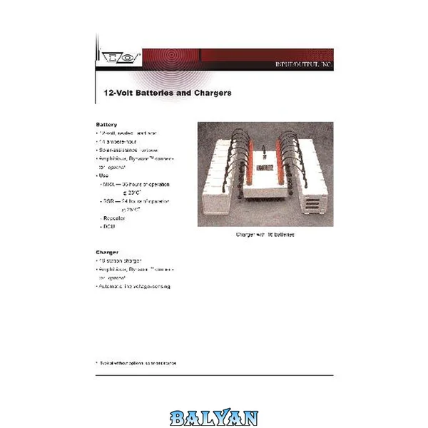
Input.Output Inc - 12-volt.batteries.and.charges
۴۹٬۰۰۰ تومان
قیمت نهایی
۴۰٬۰۰۰ تومان